
Sign up to save your podcasts
Or



At this station you can see two separate displays, one in the internal corner, and another on the external corner.
The display in the internal corner demonstrates the use of external insulation behind a rainscreen cladding. Note that in this display, the rainscreen cladding has been demonstrated in clear Perspex so you can see connections and bracketry behind. In order of installation, this display demonstrates: fire protection, vapour permeable membrane, an intumescent cavity barrier, external insulation batts, an efficient rain screen façade bracketry system, the ventilated cavity, and finally the rain screen itself. Each of these items, and the system itself will now be discussed.
This display spans across two different types of timber structure, and as such features slight differences in fire protection requirements. While the staggered stud wall to the left requires two layers of 13mm fire rated plasterboard to achieve an FRL of 90/90/90, the CLT element to the right only requires one layer of 16mm fire rated plasterboard to reach the same level. This difference in fire protection is made possible by the “massive” nature of the CLT element. While high temperatures and fire may be able to impact a stud from three sides, massive timber elements are by definition, much larger and as such are able to withstand fire loads on their own for a longer period.
While the vapour permeable membrane utilised in this display is a different product to the silver TBA Firefly product shown on the left, it ultimately performs the same function. This product – Wraptite Self Adhesive distributed by Proctor Group Australia – features a self-adhesive on one side, making an air tight envelope more easily achievable.
You may notice that there is another red element installed above the insulation batt on the left-hand side of the display. This product is an intumescent cavity barrier. Backed with a densely packed block of non-combustible insulation, this intumescent strip is designed to expand in the event of a fire, filling any cavity between the insulation and cladding, and effectively preventing any fire spread under the cladding. Note that cavity barriers may or may not be required depending on your design and have been shown in this structure purely for display purposes.
Next, you may notice the use of insulation within the façade system. In compliance with the requirement for a fire-safe façade, the insulation used in this display is non-combustible. While external insulation may or may not be required depending on your design (and the climactic conditions of the area in which your project is situated), it is important to understand it’s use and ensure it is specified where needed. External insulation is used in heating climates, where it is best practice to keep the structure warmer than external conditions, artificially elevating the dew point. This artificial elevation means that water vapour will not condense in within the structural element, instead permeating through it, and the vapour permeable membrane before cooling and forming liquid water. The insulation on display here also features a waterproof membrane to further limit the ingress of water and can be sourced from Proctor Group Australia.
The rain screen façade can be supported by a range of different brackets and frames. Here we have elected to utilise the NVelope rain screen support system, as this allows for external insulation batts to butt up to each other with minimal loss of insulated area. While an alternative system utilising top hats may achieve the same function in supporting the façade, this would leave large gaps between the insulation batts where the top hats sit resulting in an imperfect system for thermal insulation. Note that this bracket system also provides a slight gap between external insulation and cladding, allowing for a ventilated system.
Finally, the rain screen. While this display utilises Perspex, there are a wide variety of different non-combustible rain screen products available on the market today. This demonstration model shows several different rainscreen systems, although this is just a small sample of what is available on the market today.
The external corner demonstrates a vertical connection between two CLT panels. CLT panels can be produced in lengths of up to 16 metres, making it very easy to produce core panels that are two, three, or even four storeys high if you can transport them. In this structure we have utilised double height CLT panels to support installation efficiency. With tall panels come long joints, and in this structure all joints have been taped with a high-adherence non-permeable tape. This tape limits air leakage into and out of the structure, and is instrumental in delivering an air tight structure where this is sought. Note that this external corner also shows a typical angle connection between a massive timber panel and concrete slab. While the specific connector used in this location may vary depending on the design of the building, we have shown a titan angle bracket produced by Rothoblaas.
At this station you can see the outside face of the staggered stud wall. While you can see several elements discussed in station 1, here you can also note the face connector plates typically used on walls located at the slab edge. The longer steel plate on the left-hand side is designed to function in tension, and as such has been installed near the corner of the wall panel. In contrast to this, the shorter, wider steel plate on the right-hand side has been designed to function in shear and is therefore located closer to the centre of the panel. There are typically several of these plates used on every panel, with tension connectors at each corner and shear plates spaced at specified centres. Note that each of these plates has been bolted to the grey concrete slab with a concrete anchor and has been connected to the timber element with nails.
As identified earlier, this panel also features a bracing lining of OSB to laterally restrain the studs, and the fire protective linings required to achieve the required FRL.
This external face has also been treated as an external wall, and as such features a vapour permeable membrane. Note that if built, this would still require protection from rain and weather as provided by any of the rainscreen systems demonstrated on this structure.
On the outside of the non-loadbearing nib wall you can see a small display of James Hardie’s ComTex façade system, which has been designed to deliver a render finish to light weight structures. Note that the yellow façade panel here performs as a pre-primed and textured base, ready for the addition of a textured acrylic coat. When selecting a colour finish to fibre cement-based façade panels it is important to consider the light reflectance value of the colour and exposure level of the panel, as darker finishes will attract more heat in high exposure locations and may risk damaging the facade as it expands. This product requires finishing with a colour attracting a light reflectance value of at least 40, which roughly correlates to light pastel or cream shades.
A common theme amongst all the façade systems shown on this structure, the ComTex system effectively acts as a pressure-equalised rainscreen, featuring a ventilated cavity between the visual façade and the vapour permeable membrane behind. This gap allows for the natural egress of any moisture that enters the system, minimising the risk of water damage.
The vapour permeable membrane utilised behind this rainscreen has been supplied by TBA Firefly, and is classed as both vapour permeable and non-combustible. It is important to utilise a vapour permeable membrane in timber facades, as this allows moisture to permeate out of the timber system while preventing moisture from entering. While there are a number of membranes marketed as “breather membranes” it is important that any membrane used in this function is highly permeable, and supports a rate of vapour transmission of at least 4 µg/N.s. (4 micrograms per newton second).
Behind this vapour permeable membrane, you can see two layers of 13mm fire wet stop plasterboard supplied by USG Boral. Even though this wall is non-loadbearing, it is a requirement for all combustible elements utilised within a façade to be fire protected to a specified FRL.
At this station you can see two different wall types on what would be the ground floor of the seven-storey timber structure, as well as the floor system of the floor above. The wall type to the left is known as a “staggered stud” wall, referring to the staggered position of the studs on the larger bottom and top plates. This wall type is effective in reducing the transfer of vibrations from one side to the other, and as such is suitable for use where high acoustic standards are called for. Note that this wall type features double studs of Laminated Veneer Lumber or LVL at relatively close centres – this high number of studs has been specified to transfer the significant loads experienced on the lowest floor of a seven-storey structure.
Note that this staggered stud configuration doesn’t allow for the use of noggins, and as such all studs are laterally restrained by bracing sheets on each side of the panel.
This wall panel has been secured to the slab with the use of a proprietary angle bracket from connector producer Rothoblaas. As you can see, this bracket features large holes on one side to allow for concrete anchors, and smaller holes on the other to allow for nails or screws connecting to the wall panel. While this bracket is located away from the edge of the panel and is therefore intended for the transfer of shear loads, there are a variety of other bracket types throughout this structure.
Finally, you will notice that the wall is lined with two layers of 13mm fire rated plaster board. This lining has been tested and proven to achieve a Fire Resistance Level of 90/90/90, an FRL commonly required for façade or party walls.
In contrast to this robust structural wall, the nib wall to your right-hand side demonstrates the system you may find on a non-loadbearing façade wall (set back from the property boundary). While the loadbearing staggered stud wall requires double LVL studs at close centres, this non-loadbearing element is constructed of single machine graded pine studs at larger centres. Even though this element is non-loadbearing, note that as it is a façade element it must still achieve an FRL of 90/90/90 (assuming it is set back from the property boundary), explaining the two layers of 13mm.
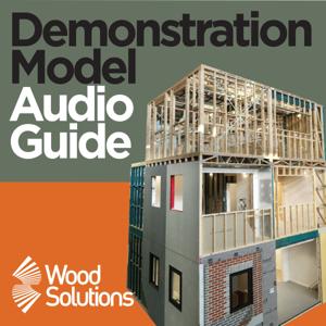
The WoodSolutions Mid-rise Demonstration Model is a mock-up of a 7 storey apartment building to illustrate details of a mid-rise project.
In this audio guide there are 23 different audio stations with examples of some of the ways you can successfully design and build a mid-rise building with engineered timber products. In three levels, you’ll see examples of the structural, fire and acoustic systems commonly found in mid-rise timber buildings.
The apartment structure is seven storeys of timber construction over a ground floor concrete podium and basement car park. The elements of the floor plan illustrated in the model include a typical apartment bedroom, bathroom, living space and stair shaft – plus an added balcony. The three levels constructed in the demonstration model reflect the differences in seven storeys of timber system construction.
The top level of the model represents the top 3 storeys of the apartment, with only single stud walls required. The centre level represents the central two story, where you’ll notice double stud walls. On the bottom floor there are triple stud walls to carry the higher load from above.
From the publisher's feed